Wika T53 User Manual
Browse online or download User Manual for Measuring instruments Wika T53. WIKA T53 User Manual
- Page / 26
- Table of contents
- BOOKMARKS
Summary of Contents
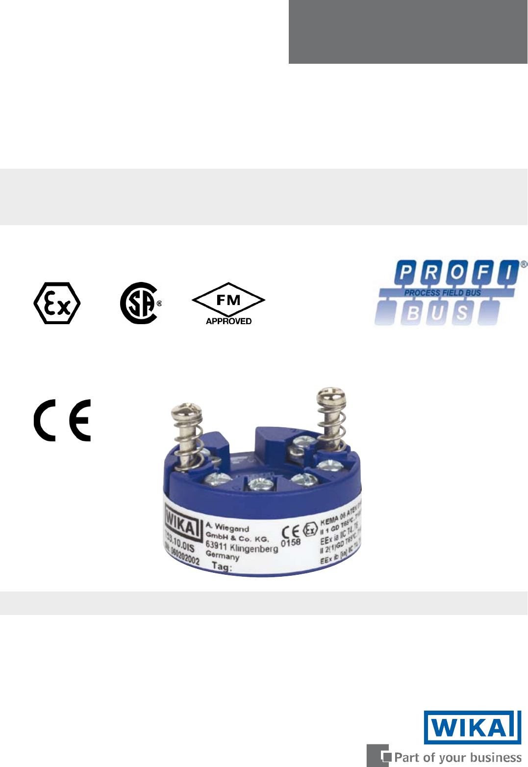
Configuration Manualfor PROFIBUS® PAFieldbus Temperature Transmitter Model T53.10for FOUNDATION™ Fieldbus and PROFIBUS® PAFieldbus Temperature Transmi
2.6.4 Measurement of thermocouple with two sensors: PRIMARY_VALUE_UNIT . . . . = K, °C, °F or °R LIN_TYPE. . . . . . . . . . . . . . . . = Any TC L
112.6.7 Measurement of resistance (linear) with two sensors: PRIMARY_VALUE_UNIT . . . . = Ohm or kOhm LIN_TYPE. . . . . . . . . . . . . . . . = No l
2.6.10 Measurement of voltage (linear) with one sensor: PRIMARY_VALUE_UNIT . . . . = µV, mV or V LIN_TYPE. . . . . . . . . . . . . . . . = No linear
TAB_XY_VALUE5 = 0,8; 300 TAB_XY_VALUE6 = 1,6; 400 TAB_XY_VALUE7 = 3,2; 500 TAB_XY_VALUE8 = 6,4; 600 TAB_XY_VALUE9 = 12,8; 700 TAB_XY_VALUE10
142.7 AI_Transducer and PR_CUST_LIN Block, SchematicRJtemp.Interntemp.INTERN_TEMPEXTERNAL_RJ_VALUELINR.J. Comp.RJ_TYPEInputINPUT1INPUT2T1T2Linearisati
2.8 AI_TRANSDUCER Block (PA Slot 3) Parameter List 2.8.1 Sensor characterising parametersParameterRel. Index PADescription Type StoreSize byteRO / R/W
16AI_TRANSDUCER Block (PA Slot 3) Parameter List2.8.2 RTD / Resistor specific parametersParameterRel. Index PADescription Type StoreSize byteRO / R/WM
17AI_TRANSDUCER Block (PA Slot 3) Parameter List2.8.4 Output conditioning parametersParameterRel. Index PADescription Type StoreSize byteRO / R/WMin.
18AI_TRANSDUCER Block (PA Slot 3) Parameter List2.8.6 Diagnostic parametersParameterRel. Index PADescription Type StoreSize byteRO / R/WMin. Max. Defa
19AI_TRANSDUCER Block (PA Slot 3) Parameter List2.8.8 Sensor calibration, DescriptionSensor calibration is a very useful function when the transmitter
2CONTENTSIntroduction . . . . . . . . . . . . . . . . . . . . . . . . . . . . . . . . . . . . . . . . . . . . . . . . . . . . . . . . . . . . 3This
20ParameterRel. Index PADescription Type StoreSize byteRO / R/WMin. Max. DefaultCAL_POINT_HI_280The high calibration value applied to sensor 2 The val
212.9 PR_CUST_LIN Block (PA Slot 4) Parameter List 2.9.1 Linear interpolation linearisation, DescriptionLinType 1 = “Linearisation Table” generates a
22ParameterRel. Index PADescription Type StoreSize byteRO / R/WMin. Max. DefaultTAB_X_Y_VALUE2354 Linearisation x,y coordinate 23Float arraySRC 8 R/W
23function is particularly suitable for specific RTD sensors but also for non-linear ohmic signals if the user can accept to enter the input and outpu
243.0 Analogue Input Blocks, Profibus3.1 Analogue Input Blocks Overview, ProfibusAnalog Input Function Blocks represent transmitters. The parameters a
253.2 Analogue Input Blocks (PA Slot 1 & 2) Parameter List, ProfibusParameterRel. IndexDescription Type StoreSize byteRO / R/WMin. Max. DefaultST_
WIKA Alexander Wiegand GmbH & Co. KGAlexander-Wiegand-Straße 3063911 Klingenberg • GermanyPhone (+49) 93 72/132-0Fax (+49) 93 72/132-406E-Mail
3IntroductionThis configuration manualcontains the necessary information for configuration of the fieldbus temperature transmit-ter T53 via a host sys
41.3 Physical Block (PA Slot 0) Parameter List, ProfibusPARAMETERRel. Index Description Type Store Size R/W Min Max DefaultST_REV1Is incremented each
52.0 The Transducer Block2.1 The Transducer Blockcontains all of the manufacturer-specific parameters that define how the T53 Transmitter functions. S
2.5 AI_Transducer Block Configuration FlowchartConfigure T53 Transducer blockTemperature measurement?SetPRIMARY_VALUE_UNITto F,R,C or KRTD?Thermo-coup
72cRTD+Thermo-couple?2bSet LIN_TYPE to TC type (TC K etc.)Set RJ_TYPE (internal, external etc.) SetSENSOR_MEAS_TYPE to dual sensor typeSet LIN_TYPE_
83b3aPotentiometer?SetPRIMARY_VALUE_UNITto ”%”SetSENSOR_CONNECTION to 3- or 4-wire. Enter wire resistance in Ohms for 2 wires to COMP_WIRE13-wire?YESE
92.6 - Transducer Block Examples Setup2.6.1 Measurement of RTD with one sensor:PRIMARY_VALUE_UNIT . . . . = K, °C, °F or °R LIN_TYPE. . . . . . . .
More documents for Measuring instruments WIKA T53


Related products and manuals for Measuring instruments Wika T53
 (37 pages)
 (24 pages)


 (100 pages)
 (20 pages)
© 2020, manymanuals.com. All rights reserved. | 1.867 s |
 Manymanuals.com
 Manymanuals.de
 Manymanuals.fr
 Manymanuals.it
 Manymanuals.pl
 Manymanuals.cz
 Manymanuals.es
 Manymanuals-pt.com
Comments to this Manuals